DIY Disclaimer
All content provided on this blog is for informational purposes only. The owner of this blog makes no representations as to the accuracy or completeness of any information on this site or found by following any link on this site. The owner will not be liable for any errors or omissions in this information nor for the availability of this information. The owner will not be liable for any losses, injuries, or damages from the display or use of this information.
About this blog post
This post is a supplement to two previous posts about building an open field maze with background illumination and using such mazes for cognitive testing in freely moving animals in a positively reinforced conditioning paradigm called the Sensory Island Task (SIT). I provide Python-based Jupyter notebooks for two variants of the task in my GitHub repository, but both notebooks communicate with self-built food dispensers via arduinos. This means, if you want to use the notebooks, you either have to modify my code to work with your own hardware or to build two of these feeders (Fig. 1) yourself.

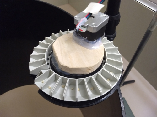
Figure 1. My SIT setup uses two of these food dispensers. They are built from automatic fish feeders and drop one reward (e.g. small pieces of peanut) per successfully completed trial. I use two alternating dispensers and solid food dropping from a height of 70 cm to reduce predictability of the reward location for the animal.
Which materials do I need for two feeders?
- arduino nano (one for both feeders)
- firmata library (downloadable for free)
- arduino uno (one per feeder)
- arduino uno compatible motor shield (one per feeder)
- motor shield library and script (downloadable for free)
- power supplies (for the arduinos and the feeders)
- stepper motor (one per feeder)
- automatic fish feeder (one per feeder)
- shrink tubing
- cables and resistors
- button (one per feeder)
- circular pieces of wood (one per feeder)
- food grade silicone sealant
- tools (soldering iron, insulation pliers, etc.)
Setting up the arduinos

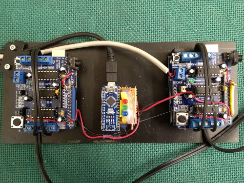
Figure 2. These are the three arduinos controlling my feeders. The arduino nano at the center position communicates with a computer via Python and sends trigger pulses to the unos with motor shields to its left and right side.
For my setup, I use three arduinos, a nano and two unos, to control two feeders (Fig. 2). The arduino nano is the one that communicates with the computer running the Jupyter notebook. If an animal makes a correct decision, the program sets a digital output channel of the arduino nano to “HIGH” for a duration of 68 ms (Fig. 3). This short voltage pulse is sent to and interpreted by one of the arduino unos with motor shield and triggers a stepper motor, which drives the belonging feeder. Please note that both arduino unos also have a button attached at the upper right corner, which allows manual activation of the feeders for calibration purposes (Fig. 2).

Figure 3. This is the code snippet from the Jupyter notebooks that activates feeder 1 of my setup as soon as the right conditions are met.
For both to work, the arduino nano only needs the Firmata library to be installed. The arduino unos, on the other hand, need a motor shield library (we use the Adafruit Motor Shield Library V1) and the “Feeder_Stepper.ino” script from my GitHub repository to be installed.
The arduino nano connects to the computer via USB. For the communication with the arduino unos, I use digital pins 12 and 4 of the arduino nano as output channels for arduino uno 1 and 2, respectively.
Each arduino uno receives its input via digital pin 2. Input to pin 2 activates the belonging stepper motor for a smooth rotation of approximately 103°. The button for manual activation of the motor is connected to digital pin 13 and allows more fine grained rotation in steps of 1.8°. Use resistors (10 kΩ) to connect both pins to ground.
Finally, the motors (e.g. MVPower 1.5 A, 2 Phase, 4-Wire Stepping Motor for 3D Printers) are connected to motor port 2 (M3 and M4) of their respective motor shield. Motors and arduino unos are powered by the same source. If you decide for the same option, place power jumpers on the motor shield. I use a single 5 V power source (Anker PowerPort 5; 2.4 A per port) for both arduinos/motors.
Connecting the motors to the feeders
For the feeders themselves, we use commercially available, automatic fish feeders, from which we remove the timer and replace the original motor with our stepper motor. The model we use is the Rondomatik 400 (Grässlin GmbH, St. Georgen, Germany), but there are probably similar feeders from other manufacturers. We decided for this model, as it is easy to clean and it comes with a mount to fix it to an aquarium wall (or to the wall of an open field maze). Also, each feeder has 27 individual “food bowls”, so that two of these feeders suffice to provide 50 rewards without the need for a refill.
Once the timer has been removed, connect an appropriate gear of the remaining “clockwork” of the feeder to your motor, so that every rotation of the motor is directly transferred to the clockwork (Fig. 4). For this, we use shrink tubing as connector between gear and motor. If you are happy with the transmission, use a wooden disk and lots of food grade silicone sealant to fix the stepper motor (which is quite heavy) in place (Fig. 1).

Figure 4. If you use the same feeder model as I do, the innards should look similar to this sketch. Using shrink tubing, I connected the motor to the most peripheral gear (yellow), as its rotation is directly trasnmitted to the carousel with the food bowls (via the green gear).
Adjusting the code
If you are done tinkering, it is time to test your feeder and to make some adjustments to the arduino script, if necessary. The script was written for the combination of our motor model with a step angle of 1.8° and our feeder with 27 food slots. The trigger pulse activates the motor for 57 steps (or 102.6°), which translates to a rotation of the feeder of approximately 7°, so that exactly one of the reward bowls is emptied. If you use a different stepper motor and/or feeder model, you will have to adjust the number of steps the motor rotates per trigger pulse in the arduino script (Fig. 5).

Figure 5. In line 30 of the arduino script, you can change the number of steps the motor rotates each time it gets activated.